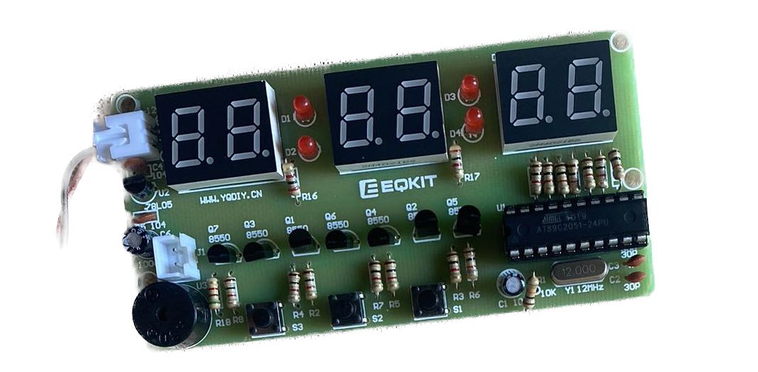
Mark Zhang

Engineering Documentation

Alarm Clock

October 13th, Friday, 2023

During this week, I learned necessary skills to make an alarm clock. The design process involves soldering, Fusion 360 modeling, Prusa Slicer parameter adjustment, and printing calibration

Interactive index

Soldering Measurements and design 1st try Elaboration Prints and iterations Prints and iterations cont. Final product Slicer Settings Troubleshooting & reflection

Soldering

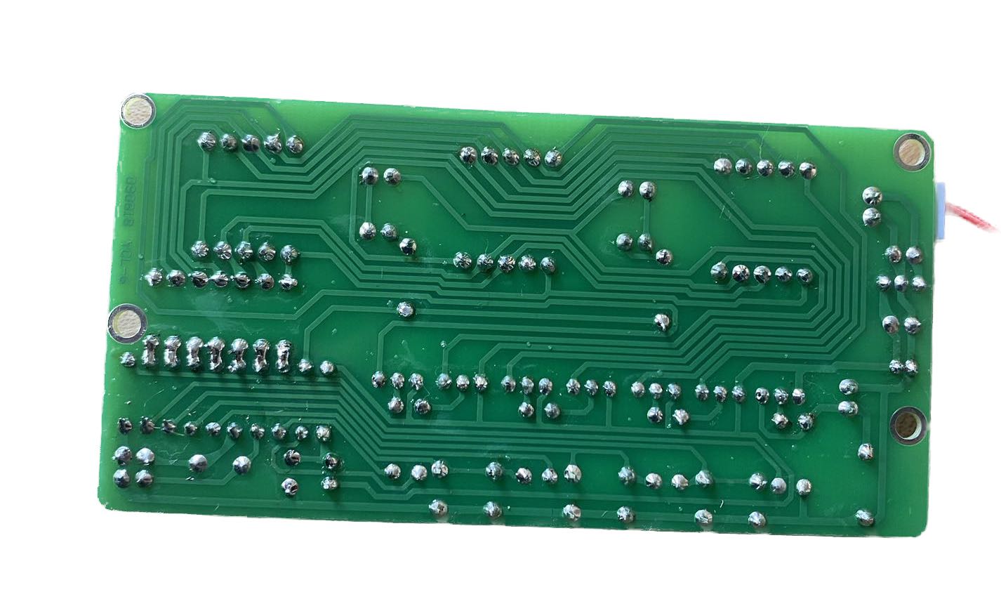
The first step is to solder the kit. I had some prior soldering experience, though it dates back to my primary school days when I used to be a member of the electronics club. Nevertheless, I was a bit apprehensive about it since it had been a while, and I still remembered getting burned by the soldering iron. However, it didn't take me too long to regain this skill. The outcome was great. One important technique for achieving beautiful soldering points is not to linger too long on a single spot; a small amount of solder at the tip is sufficient to create a brilliant, flat soldering point. I once got some bulky soldering points, but the 'redo' tool helpe me a lot. One tip of the 'redo' tool is that you have to put it really close to the soldering point otherwise it won't be effective.

Measurements and design

My partner and I took all the potentially useful measurements of the kit, including the dimensions of buttons, displays, batteries, etc., to ensure they would fit within the cover we designed. Subsequently, we devised a straightforward design for the container box, complete with openings for the displays and buttons. Inside the box, we included a rod to stabilize the kit and connect the cover to the base. Taking these measurements, though quite laborious out of context, proved to be an important step in the process. Later my partner came up with the idea of an additional bee-hive shell to enwrap this simple design.

1st try

We had a first try to just test out the dimensions we measured. This one was made intentionally simple. Soon we had it printed out. Most dimensions fitted but we should have considered tolerance. Therefore, in the later designs we always kept that in mind: make slots and holes a little bit bigger than what we've measured.

Elaboration

After obtaining the adjusted dimensions, we began developing more intricate designs. We constructed the body, ensuring that the body fit snugly within the cover. We created several versions of the design: I worked on a flat cover with a concave slot, connected by an extruded rod from the flat cover, while my partner crafted a cover with a shell extrusion. We discovered that this refinement process was more efficient when each of us worked on separate versions to determine which one was better.

Prints and iterations

This process required patience and multiple iterations, which resulted in numerous failed prints. The first one suffered from poor bridging due to inappropriate slicer settings, particularly the absence of a raft layer and inadequate inner support. However, even though it was undoubtedly a failure, it served as a valuable parameter to assess the fit of our holes.

Prints and iterations cont.

However, we soon realized that we had forgotten to allocate space for the battery. This prompted us to go back and redesign it before printing again. A new issue surfaced when we found that the hole for the battery connector was too small to allow it to pass through.In addition, our bee-hive model encountered a peculiar problem. We were using a Prusa MINI, and it printed halfway before stopping. As a result, we had to wait for days to reprint it. The entire process demanded time and effort as we struggled and learned from these challenges.

Final product

Gladly, we eventually emerged from the arduous iterations! We obtained a stylish bee-hive shell and a body that fits perfectly (albeit with some minor printing issues, most likely due to poor bridging and insufficient support). We also managed to create an individual, straightforward version with a well-fitting battery container. Well, except for a minor mishap that the rod extruded the wrong way, shhh let's just pretend you didn't notice that. :) I actually tested that rod, it actually fits in the hole I reserved on the body and could go through the hole on the kit board. So if I flip it and reprint it everything will be fine, hopefully.

Slicer Settings

I used PrusaSlicer because I'm using a Prusa MINI, not a Prusa i3 MK3. Since we consistently encountered the issue of poor bridging, during the last print, I activated the 'detect bridging parameter' in the Layers and Parameters settings. As a safety measure, I opted for support throughout the print. The drawback of this choice is that it can lead to support structures that are challenging to remove and relatively time-consuming. Next time, I plan to try disabling the 'fill gaps' feature, which should make it easier to remove any remaining support materials lodged in the small notches. The raft feature was test to be so useful as a safety approach. I had 2 raft layers and the contact z distance was 0.15mm.

Troubleshooting & reflection

Aside from the issues I've mentioned before, we encountered a rare problem with our kit board. When we initially finished soldering and assembling it, everything lit up perfectly. However, several days later, it ceased to function. I consulted with my professors regarding my soldering points, and they confirmed they were well-done. Vincent then helped us inspect the voltage flow throughout the circuit and didn't identify anything particularly suspicious. My suspicion is that the issue might be related to poor contact with the battery wires. I also used to struggle with adjusting the dimensions, often specifying too many values and creating driven dimensions that had no practical meaning. However, after mastering the parameter feature, I found it easy to simultaneously manipulate a group of relative values by adjusting one or several parameters. The iteration process is indeed strenuous, but it's a necessary step for every engineering project. Next time, I should try to be more patient, understanding that the eventual outcome will be great. Picking up the soldering is also fun. Watching neatly aligned soldering points is indeed satisfying.

Copyright © Mark Zhang 2023